All Cisco configurations

Cisco How To's

All Cisco Configurations: July 2011

Thursday, July 14, 2011

OSPF Theory

OSPF Concepts, Area Design and Terms

Hello Everyone this is Open Shortest Path First(OSPF) Routing protocol Post:

Before moving ahead I request you to please see my Route summarization post here  , as it is utterly important to understand route summarization first. There is no point in applying Routing protocols like
ospf and eigrp without applying route summarization. so please first understand route summarization.

Lets first get familiar about ospf and its terms. OSPF is a link state routing protocol. Unlike distance vector routing protocols like RIP, link state routing protocol only sends changes to its neighbor routers. ( Remember in
RIP routing,router broadcast all their routing information saying " Hello I know about so and so routes" at certain intervals rather than forming neighbor relationship with other routers) . Link state routing protocols first establish neighbor relationship with its neighbors
and then only send changes as updates.

please refer to the below mentioned figures you can click to enlarge the figure

Ospf theory,area designs and terms


AREA: An area in ospf is a group of all routers that all have the same routing information. Cisco recommends this area to have no
more than 50 routers. Inside of Area, there are
1> Internal Routers: Routers that only knows about the specific area. eg in the figure the routers in area 0 knows all about the area 0.
All routers in an area have the same topology table(Roadmap) i.e all of the routers in area 0 knows everything
about the area, but every router within an area may have different routing table.
2> Autonomous Border Routers(ABR): Routers that sits between routers in the same autonomous system. ABR is responsible for
routing between different areas of the same autonomous system i.e ABR is the one that is able summarize.
3>Autonomous System Boundary Router(ASBR): is the one that connects different autonomous system. This ASBR can also summarize the route and advertise to different autonomous system

All Area Must connect to Area 0 ( backbone router). when designing ospf, it has to be a hierarchical designs ie have to group similar
subnets in similar areas.

OSPF Neighbor Relationship
A router running ospf forms neighbor relationship with other router by sending HELLO Messages on the chosen interface
1> once every 10 sec on broadcast/p-2-p networks
2>once every 30 sec on NBMA networks ( we will later discuss NBMA networks)

Hello contains all of the below information:
1>Router I.D : its like the name of the name of the router
2>Hello and Dead timers* : How often the these hello messages should be exchanged and the time after which if no hello messages
is received the neighbor is considered dead
3>Network Mask*: Network mask the router advertises
4>Area ID*:
5>Neighbors*:
6>Route Priority:
7>DR/BDR IP address:
8>Authentication Password*:

The * sign mean that these fields must match between two routers to talk with ospf language.

ok now we are ready to delve into ospf configuration. So In my next post we will configure a simple multi-area ospf and later move into the advanced topics. so stay on

Thank you
Ciscohowtos

Tuesday, July 12, 2011

Route Summarization

Route Summarization: Route summarization is all about making the routing table smaller. The larger the routing table the inefficient the router becomes i.e when the packet
comes/goes out of the router the router has to check against all the routing table entries and find the best routes. route summarization shrinks the routing table. I want to illustrate route summarization
from the below figures

Route Summarization
In the figure above router R1 sends all the 16 routes to router R2 and R2 sends all these routes to other corporate network if connected. Now R2 has
1> R2 has routes of all the destination that R2 has to anyway go to R1 to reach
2>If one of the network say 192.168.3.0/24 goes down then it needs to update and replicate to R2 and R2 has to replicate it to others.

Now, the question is Does R2 really need to know that 192.168.3.0/24 network is down. Well I dont think so, becoz when R2 sends packets to 192.168.3.0/24 networks it will sends these packets to
R1. Then R1 will reply with ICMP unreachable. What I mean to say is router R1 will take care of any packet going to that network.

Lets imagine if we can shrink the 16 routes of R1 somehow. This is done by route summarization. Route summarization summarizes all the routes of R1 to fewer advertisements
What we can summarize the route in R1 as 192.168.0.0/16( as now this contains all the 16 routes) network and now R1 advertises this route to R2. Now R1 supresses all the individual route.
But the problem here is If we summarize R1 route as 192.168.0.0/16 then we are wasting all the network beyond 192.168.15.0/24 and no other router can use other network in 192.168.0.0/16.
This is what I call inefficient summarization.

Efficient Summarization
Lets summarize this 192.168.0.0 ---- 192.168.0.15/24 network.

I have broken down all our networks in bits so that it will become easier to visualize the summarization process. The idea of route summarization is to take the bits that are similar/same between all of the routes and
grouped them together. Now if we see our routes
1st 192 octet is same ie 1st 8bits are same
2nd 168 octet is same ie 2nd 8 bits are same
and then 4 bits of third octet are same and from then it starts to differ. I have shown this by drawing a line
So We now have 20 bits same so the perfect route advertisement from R1 to R2 would be 192.168.0./20 is 255.255.240.0 S.M
192.168.0.0 255.255.240.0
11111111.11111111.11110000.00000000
 last increment bit = 16
 so our network will be
        192.168.0.0   ----------> 192.168.15.0
         192.168.16.0  ---------->192.168.31


Now if we reverse engineer the /20 subnet mask as shown above then we will find that /20 is fit for out 15 network route

what If one more network is added lets say one more network 192.168.16.0 is added. Now if we see just like from above the similar bits are 19 bits. So according to this we have to advertise 192.168.0.0/19 which will
give us 32 networks that means the router can use 192.168.0.0 --- > 192.168.31.0 networks. but we dont need networks above 192.168.19.0. ie networks beyond 192.168.19.0 is wasted. So the best way to deal with
this growth scenario would be to keep on advertising the 192.168.0.0/20 network and advertise 192.168.16.0/24 network as a seperate route until there is enoubh addition of networks to change ti to 192.168.0.0/19 network.


This is all about route summarization Hope you have understand this. Route summarization will be very helpful when we are doing link state routing protocols like ospf and eigrp.
Thanks and I'll hope to see you soon

Thursday, July 7, 2011

RIP routing with nat overload

How to : Rip Routing

Rip Routing with nat overload
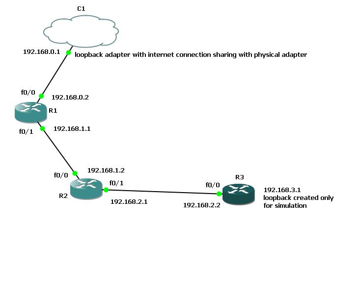
In this post we will be doing RIP routing, static routing and NAT overload. In the Figure
R! : is the router which is connected to internet through my loopback adapter ( Please see earlier post  to see how to configure gns3 and static routing here.) We will be applying rip router in all the three routers so that three routers can have connection to each other. Along with this we will
configure SNAT overload in router R1 so that R2 and R3 also have internet connection through router R1
Remember this is all done in GNS3 with 2691 router image


Configuration on router R1

R1>en
R1#config t
Enter configuration commands, one per line.  End with CNTL/Z.
R1(config)#inter
R1(config)#interface fa
R1(config)#interface fastEthernet 0/0
R1(config-if)#ip address 192.168.0.2 255.255.255.0
R1(config-if)#no shutdown
R1(config-if)#exit
R1(config)#int
*Mar  1 00:01:30.675: %LINK-3-UPDOWN: Interface FastEthernet0/0, changed state to up
*Mar  1 00:01:31.675: %LINEPROTO-5-UPDOWN: Line protocol on Interface FastEthernet0/0, changed state to up
R1(config)#interfa
R1(config)#interface fa
R1(config)#interface fastEthernet 0/1
R1(config-if)#ip address 192.168.1.1 255.255.255.0
R1(config-if)#no shutdown
R1(config-if)#exit
R1(config)#exit
R1#
*Mar  1 00:03:12.987: %LINK-3-UPDOWN: Interface FastEthernet0/1, changed state to up
R1#
*Mar  1 00:03:13.703: %SYS-5-CONFIG_I: Configured from console by console
*Mar  1 00:03:13.987: %LINEPROTO-5-UPDOWN: Line protocol on Interface FastEthernet0/1, changed state to up
R1#config t
Enter configuration commands, one per line.  End with CNTL/Z.
R1(config)#ip route 0.0.0.0 0.0.0.0 192.168.0.1
R1(config)#exit
R1#ping 1
*Mar  1 00:03:35.171: %SYS-5-CONFIG_I: Configured from console by console
R1#ping 192.168.0.1

Type escape sequence to abort.
Sending 5, 100-byte ICMP Echos to 192.168.0.1, timeout is 2 seconds:
.!!!!
Success rate is 80 percent (4/5), round-trip min/avg/max = 16/21/32 ms
R1#ping 8.8.8.8

Type escape sequence to abort.
Sending 5, 100-byte ICMP Echos to 8.8.8.8, timeout is 2 seconds:
!!!!!
Success rate is 100 percent (5/5), round-trip min/avg/max = 216/256/308 ms
R1#ip na
R1#config t
Enter configuration commands, one per line.  End with CNTL/Z.
R1(config)#ip name
R1(config)#ip name-server 8.8.8.8
R1(config)#ip dom
R1(config)#ip domain-l
R1(config)#ip domain-loo
R1(config)#ip domain-lookup
R1(config)#exit
R1#ping
*Mar  1 00:04:13.827: %SYS-5-CONFIG_I: Configured from console by console
R1#ping www.google.com
Translating "www.google.com"...domain server (8.8.8.8) [OK]

Type escape sequence to abort.
Sending 5, 100-byte ICMP Echos to 74.125.235.52, timeout is 2 seconds:
!!!!!
Success rate is 100 percent (5/5), round-trip min/avg/max = 156/175/236 ms

The above configuration shows that we have internet access from router R!
Now lets configure rip routing in R1 so that other routers knows about 192.168.0.0 and 192.168.1.0 network

R1(config)#router ri
R1(config)#router rip
R1(config-router)#ver
R1(config-router)#version 2
R1(config-router)#no au
R1(config-router)#no auto-summary
R1(config-router)#network 192.168.0.0
R1(config-router)#network 192.168.1.0

Now you can do
R1#sh ip protocols
Routing Protocol is "rip"
  Sending updates every 30 seconds
  Invalid after 180 seconds, hold down 180, flushed after 240
  Outgoing update filter list for all interfaces is not set
  Incoming update filter list for all interfaces is not set
  Redistributing: rip
  Default version control: send version 2, receive version 2
    Interface             Send  Recv  Triggered RIP  Key-chain
    FastEthernet0/0       2     2
    FastEthernet0/1       2     2
  Automatic network summarization is not in effect
  Maximum path: 4
  Routing for Networks:
    192.168.0.0
    192.168.1.0
  Routing Information Sources:
    Gateway         Distance      Last Update
  Distance: (default is 120)
This shows that router rip is running and sending updates every 30 seconds

Now lets move to Router R2
R2>en
R2#config t
Enter configuration commands, one per line.  End with CNTL/Z.
R2(config)#interfa
R2(config)#interface fa
R2(config)#interface fastEthernet 0/0
R2(config-if)#ip add
R2(config-if)#ip address 192.168.1.2 255.255.255.0
R2(config-if)#no shu
R2(config-if)#no shutdown
R2(config-if)#exit
*Mar  1 00:03:18.119: %LINK-3-UPDOWN: Interface FastEthernet0/0, changed state to up
*Mar  1 00:03:19.119: %LINEPROTO-5-UPDOWN: Line protocol on Interface FastEthernet0/0, changed state to up
R2(config-if)#exit
R2(config)#exit
R2#config t
Enter configuration commands, one per line.  End with CNTL/Z.
R2(config)#
*Mar  1 00:03:20.823: %SYS-5-CONFIG_I: Configured from console by console
R2(config)#interf
R2(config)#interface fa
R2(config)#interface fastEthernet 0/1
R2(config-if)#ip address 192.168.2.1 255.255.255.0
R2(config-if)#no shutdown
R2(config-if)#
*Mar  1 00:03:49.651: %LINK-3-UPDOWN: Interface FastEthernet0/1, changed state to up
*Mar  1 00:03:50.651: %LINEPROTO-5-UPDOWN: Line protocol on Interface FastEthernet0/1, changed state to up
R2(config-if)#exit
R2(config)#router rip
R2(config-router)#vers
R2(config-router)#version 2
R2(config-router)#no au
R2(config-router)#no auto-summary
R2(config-router)#network 192.168.1.0 192.168.2.0
                                      ^
% Invalid input detected at '^' marker.

R2(config-router)#network 192.168.1.0
R2(config-router)#network 192.168.2.0
R2(config-router)#exit
R2(config)#exit
R2#
*Mar  1 00:04:49.815: %SYS-5-CONFIG_I: Configured from console by console
R2#sh ip route
Codes: C - connected, S - static, R - RIP, M - mobile, B - BGP
       D - EIGRP, EX - EIGRP external, O - OSPF, IA - OSPF inter area
       N1 - OSPF NSSA external type 1, N2 - OSPF NSSA external type 2
       E1 - OSPF external type 1, E2 - OSPF external type 2
       i - IS-IS, su - IS-IS summary, L1 - IS-IS level-1, L2 - IS-IS level-2
       ia - IS-IS inter area, * - candidate default, U - per-user static route
       o - ODR, P - periodic downloaded static route

Gateway of last resort is not set

R    192.168.0.0/24 [120/1] via 192.168.1.1, 00:00:08, FastEthernet0/0
C    192.168.1.0/24 is directly connected, FastEthernet0/0
C    192.168.2.0/24 is directly connected, FastEthernet0/1

Above you can see that router R2 now knows about 192.168.0.0 network through rip running on router R!
Now lets see if we can ping 192.168.0.2
R2#ping 192.168.0.2

Type escape sequence to abort.
Sending 5, 100-byte ICMP Echos to 192.168.0.2, timeout is 2 seconds:
!!!!!
Success rate is 100 percent (5/5), round-trip min/avg/max = 96/176/216 ms
yes we can
ok lets try to ping 192.168.0.1
Type escape sequence to abort.
Sending 5, 100-byte ICMP Echos to 192.168.0.1, timeout is 2 seconds:
.....
Success rate is 0 percent (0/5)
oh the ping is failing why? remember our 192.168.0.1 is connected through internet so we have to perform nat so that all the packets to 192.168.0.1 should come from 192.168.0.2
we will be performing nat later, for now lets move to router R3 and configure RIP there

R3
R3>en
R3#config t
Enter configuration commands, one per line.  End with CNTL/Z.
R3(config)#interface fas
R3(config)#interface fastEthernet 0/0
R3(config-if)#ip address 192.168.2.2 255.255.255.0
R3(config-if)#exit
R3(config)#inter
R3(config)#interface lo
R3(config)#interface loopback ?
  <0-2147483647>  Loopback interface number

R3(config)#interface loopback 0
R3(config-if)#ip address 192.168.3.1
% Incomplete command.

R3(config-if)#ip address 192.168.3.1 255.255.255.0
R3(config-if)#no shut
R3(config-if)#exit
R3(config)#router rip
R3(config-router)#version 2
R3(config-router)#no au
R3(config-router)#no auto-summary
R3(config-router)#network 192.168.2.0
R3(config-router)#network 192.168.3.0
R3(config-router)#exit
R3(config)#exit
R3#sh ip
*Mar  1 00:11:40.659: %SYS-5-CONFIG_I: Configured from console by console
R3#sh ip route
Codes: C - connected, S - static, R - RIP, M - mobile, B - BGP
       D - EIGRP, EX - EIGRP external, O - OSPF, IA - OSPF inter area
       N1 - OSPF NSSA external type 1, N2 - OSPF NSSA external type 2
       E1 - OSPF external type 1, E2 - OSPF external type 2
       i - IS-IS, su - IS-IS summary, L1 - IS-IS level-1, L2 - IS-IS level-2
       ia - IS-IS inter area, * - candidate default, U - per-user static route
       o - ODR, P - periodic downloaded static route

Gateway of last resort is not set

C    192.168.3.0/24 is directly connected, Loopback0
R3#config t
Enter configuration commands, one per line.  End with CNTL/Z.
R3(config)#inter
R3(config)#interface f
R3(config)#interface fastEthernet 0/0
R3(config-if)#no shutdown
R3(config-if)#exit
R3(config)#exit
R3#
*Mar  1 00:12:06.791: %LINK-3-UPDOWN: Interface FastEthernet0/0, changed state to up
R3#
*Mar  1 00:12:06.963: %SYS-5-CONFIG_I: Configured from console by console
*Mar  1 00:12:07.791: %LINEPROTO-5-UPDOWN: Line protocol on Interface FastEthernet0/0, changed state to up
R3#sh ip route
Codes: C - connected, S - static, R - RIP, M - mobile, B - BGP
       D - EIGRP, EX - EIGRP external, O - OSPF, IA - OSPF inter area
       N1 - OSPF NSSA external type 1, N2 - OSPF NSSA external type 2
       E1 - OSPF external type 1, E2 - OSPF external type 2
       i - IS-IS, su - IS-IS summary, L1 - IS-IS level-1, L2 - IS-IS level-2
       ia - IS-IS inter area, * - candidate default, U - per-user static route
       o - ODR, P - periodic downloaded static route

Gateway of last resort is not set

C    192.168.2.0/24 is directly connected, FastEthernet0/0
C    192.168.3.0/24 is directly connected, Loopback0
R3#sh ip route
Codes: C - connected, S - static, R - RIP, M - mobile, B - BGP
       D - EIGRP, EX - EIGRP external, O - OSPF, IA - OSPF inter area
       N1 - OSPF NSSA external type 1, N2 - OSPF NSSA external type 2
       E1 - OSPF external type 1, E2 - OSPF external type 2
       i - IS-IS, su - IS-IS summary, L1 - IS-IS level-1, L2 - IS-IS level-2
       ia - IS-IS inter area, * - candidate default, U - per-user static route
       o - ODR, P - periodic downloaded static route

Gateway of last resort is not set

R    192.168.0.0/24 [120/2] via 192.168.2.1, 00:00:23, FastEthernet0/0
R    192.168.1.0/24 [120/1] via 192.168.2.1, 00:00:23, FastEthernet0/0
C    192.168.2.0/24 is directly connected, FastEthernet0/0
C    192.168.3.0/24 is directly connected, Loopback0

Now upto this point we have connectivity to all the routers, you can check by doing ping

Now if you see sh ip route in R1, R2 and R3 you can see that In R1 the gateway of last resort is set but in R2 and R3 you will find gateway of last resort not set
what this means is route R2 and R3 knows about 192.168..0.0 192.168.1.0 192.168.2.0 192.168.3.0 through direct connection and through rip routing, but it doesnt know any other networks than that.
so if we ping 8.8.8.8 then these two routers will look up in their routing table and drops the packet as both routers does not know about 8.8.8.8 networks. so we have to give them the default route so that
the routers can route all other packets other than the network they knows from direct connection and rip routing. In other words lets define their default gateways

R2(config)#ip route 0.0.0.0 0.0.0.0 192.168.1.1
R3(config)#ip route 0.0.0.0 0.0.0.0 19.168.2.1

Ok now lets configure NAT overload in router R1 so that routers R2 and R3 can connect to the internet

NAT
R1>en
R1#config t
Enter configuration commands, one per line.  End with CNTL/Z.
R1(config)#int fa
R1(config)#int fastEthernet 0/0
R1(config-if)#ip nat outside
R1(config-if)#int fa
R1(config-if)#exit
R1(config)#int
R1(config)#interface fa
R1(config)#interface fastEthernet 0/1
R1(config-if)#ip nat inside
R1(config-if)#exit
R1(config)#ip access
R1(config)#ip access-list sta
R1(config)#ip access-list standard NAT_ADDRESSES
R1(config-std-nacl)#permit 192.168.0.0 0.0.255.255
R1(config-std-nacl)#exit
R1(config)#exit
R1#show ac
*Mar  1 00:18:21.811: %SYS-5-CONFIG_I: Configured from console by console
R1#show acc
R1#show acce
R1#show access-li
R1#show access-lists
Standard IP access list NAT_ADDRESSES
    10 permit 192.168.0.0, wildcard bits 0.0.255.255
R1#ip nat inside sour
R1#config t
Enter configuration commands, one per line.  End with CNTL/Z.
R1(config)#ip na
R1(config)#ip nat ins
R1(config)#ip nat inside sou
R1(config)#ip nat inside source li
R1(config)#ip nat inside source list NAT_ADDRESSES int
R1(config)#ip nat inside source list NAT_ADDRESSES interface fa
R1(config)#$de source list NAT_ADDRESSES interface fastEthernet 0/0 over
R1(config)#$de source list NAT_ADDRESSES interface fastEthernet 0/0 overload

no routers R2 and R3 can have internet connection

R2(config)#ip nam
R2(config)#ip name-server 8.8.8.8
R2(config)#ip dom
R2(config)#ip domain-l
R2(config)#ip domain-lo
R2(config)#ip domain-lookup
R2#ping www.google.com
Translating "www.google.com"...domain server (8.8.8.8) [OK]

Translating "www.google.com"...domain server (8.8.8.8) [OK]

Translating "www.google.com"...domain server (8.8.8.8) [OK]

Type escape sequence to abort.
Sending 5, 100-byte ICMP Echos to 74.125.235.51, timeout is 2 seconds:
!!!!!
Success rate is 100 percent (5/5), round-trip min/avg/max = 240/383/572 ms
You can see nat translations in router R!
R1#sh ip nat translations
Pro Inside global      Inside local       Outside local      Outside global
udp 192.168.0.2:55090  192.168.1.2:55090  8.8.8.8:53         8.8.8.8:53
icmp 192.168.0.2:7     192.168.1.2:7      8.8.8.8:7          8.8.8.8:7
icmp 192.168.0.2:4     192.168.1.2:4      192.168.0.1:4      192.168.0.1:4
icmp 192.168.0.2:8     192.168.1.2:8      192.168.0.1:8      192.168.0.1:8
udp 192.168.0.2:51837  192.168.1.2:51837  8.8.8.8:53         8.8.8.8:53
udp 192.168.0.2:56093  192.168.1.2:56093  8.8.8.8:53         8.8.8.8:53
udp 192.168.0.2:520    192.168.0.2:520    224.0.0.9:520      224.0.0.9:520
udp 192.168.0.2:56675  192.168.1.2:56675  8.8.8.8:53         8.8.8.8:53
icmp 192.168.0.2:3     192.168.1.2:3      74.125.235.51:3    74.125.235.51:3
icmp 192.168.0.2:6     192.168.1.2:6      74.125.235.48:6    74.125.235.48:6
icmp 192.168.0.2:5     192.168.1.2:5      74.125.235.52:5    74.125.235.52:5
udp 192.168.0.2:52606  192.168.1.2:52606  8.8.8.8:53         8.8.8.8:53
udp 192.168.0.2:52811  192.168.1.2:52811  8.8.8.8:53         8.8.8.8:53

Thank you

Cisco How to : Cisco Routing Configurations

How to Configure Static routing


First of all lets configure static routing in the form of default routing on the cisco routers. This lab is done in gns3 and with 2691 router series on Microsoft Windows Xp.

What we are going to do in this lab is we will connect our routers running inside gns3 to the internet through Microsoft loopback adapter.

Detailed description of the diagram:

As you can see in the figure , There is an internet cloud which i have used to represent internet connection. I have attached microsoft loopback adapter to this cloud and

Configured Internet connection sharing between the physical interface (ie interface connected to the internet physically) and loopback adapter. so that my loopback adapter

is connected to the internet. (note: do not configure your physical interface with ip range 192.168.0.0/24 as this is the range given to loopback adapter while configuring internet

connection sharing). The loopback adapter is connected to our router R1.. We will be configuring static routing in this router as a result the router can connect to internet. We will

test this by sending ping packets to various sites on the internet.

Configuration

1> Lets first create a loopback adapter and give it a name internetconnection

Go to Start -->Run--->type hdwwiz.cpl (shortcut to hardware addition wizard) ---->Next

Select Yes I have already added the hardware and click next

select Add a new hardware device and click next

select install the hardware that i manually select from the list and click next

select Network adapters and then select Microsoft Loopback adapter and click next

Click Next and finish

Go to Start-->Run--->type ncpa.cpl and rename the loopback adapter to internet connection

2> Now that we have configured loopback adapter lets configure internet connection sharing to this loopback adapter from physical interface

Here I am sharing my wireless connection to loopback (But you can share your physical connection)

Go to Start--->Run----> ncpa.cpl and select your physical connection

Right click your physical connection and go to properties --- >Advanced ---> Select Allow other users to connect to internet through

this network interface --- > ok

3> Now goto GNS3

drag router 2691 and cloud to the console

Right click the cloud and goto to configuration

In the configurator node on the left select C1 and on the right in NIO ethernet tab select loopback adapter from list of available adapters and

click add and then click apply

Now from the top menu select Add a link and connect the cloud to routers fa0/0 interface

4>Right click the router and do start

Right click the router and go to console

now do the following ( note before going to below configuration if you are new to this site then please refer

my basic cisco device configuration section here Basic Cisco Device Configuration


R2>

R2>en

R2#config t

Enter configuration commands, one per line. End with CNTL/Z.

R2(config)#inter

R2(config)#interface fa

R2(config)#interface fastEthernet 0/0

R2(config-if)#ip address 192.168.0.2 255.255.255.0

R2(config-if)#no shutdown

R2(config-if)#exit

R2(config)#e

*Mar 1 00:00:54.611: %LINK-3-UPDOWN: Interface FastEthernet0/0, changed state to up

*Mar 1 00:00:55.611: %LINEPROTO-5-UPDOWN: Line protocol on Interface FastEthernet0/0, changed state to up

R2(config)#exit

R2#ping

*Mar 1 00:00:57.211: %SYS-5-CONFIG_I: Configured from console by console

R2#ping 192.168.0.1

Type escape sequence to abort.

Sending 5, 100-byte ICMP Echos to 192.168.0.1, timeout is 2 seconds:

.!!!!

Success rate is 80 percent (4/5), round-trip min/avg/max = 20/26/32 ms

above we have given the ip 192.168.0.2/24 to router interface fastethernet 0/0 and we have connectivity to the clouds/loopback address ( remember to disable all the firewalls

and disble the antivirus because sometime antivirus will block network traffic)

Now lets try to ping to internet

R2#ping 8.8.8.8

Type escape sequence to abort.

Sending 5, 100-byte ICMP Echos to 8.8.8.8, timeout is 2 seconds:

.....

Success rate is 0 percent (0/5)

above I have tried to ping 8.8.8.8 which is googles name server and it clearly shows that the ping is failing.

If we do R2#show ip route

Codes: C - connected, S - static, R - RIP, M - mobile, B - BGP

D - EIGRP, EX - EIGRP external, O - OSPF, IA - OSPF inter area

N1 - OSPF NSSA external type 1, N2 - OSPF NSSA external type 2

E1 - OSPF external type 1, E2 - OSPF external type 2

i - IS-IS, su - IS-IS summary, L1 - IS-IS level-1, L2 - IS-IS level-2

ia - IS-IS inter area, * - candidate default, U - per-user static route

o - ODR, P - periodic downloaded static route

Gateway of last resort is not set

C 192.168.0.0/24 is directly connected, FastEthernet0/0

then the result clearly shows that the router only knows how to reach 192.168.0.0/24 network and any other netoworks the router doesnt know about.

So Now here we have to configure static routing on the router by doing

R2#config t

Enter configuration commands, one per line. End with CNTL/Z.

R2(config)#ip route 0.0.0.0 0.0.0.0 192.168.0.1 (This tells the router that to reach any network i.e 0.0.0.0/0.0.0.0 forward the packet to 192.168.0.1 and since we have shared our internet connection packets will be

forwarded to the internet

now check the router routing table, you wll find the newly added route

R2#show ip route

Codes: C - connected, S - static, R - RIP, M - mobile, B - BGP

D - EIGRP, EX - EIGRP external, O - OSPF, IA - OSPF inter area

N1 - OSPF NSSA external type 1, N2 - OSPF NSSA external type 2

E1 - OSPF external type 1, E2 - OSPF external type 2

i - IS-IS, su - IS-IS summary, L1 - IS-IS level-1, L2 - IS-IS level-2

ia - IS-IS inter area, * - candidate default, U - per-user static route

o - ODR, P - periodic downloaded static route

Gateway of last resort is 192.168.0.1 to network 0.0.0.0

C 192.168.0.0/24 is directly connected, FastEthernet0/0

S* 0.0.0.0/0 [1/0] via 192.168.0.1

Now the ping will reach the destination

R2#ping 8.8.8.8

Type escape sequence to abort.

Sending 5, 100-byte ICMP Echos to 8.8.8.8, timeout is 2 seconds:

!!!!!

Success rate is 100 percent (5/5), round-trip min/avg/max = 360/374/396 ms

you can also give name server to the router and ping using names like www.google.com by doing

R2(config)#ip na

R2(config)#ip nam

R2(config)#ip name-server 8.8.8.8

R2(config)#ip do

R2(config)#ip domain-loo

R2(config)#ip domain-lookup

R2(config)#exit

R2#ping

*Mar 1 00:11:04.923: %SYS-5-CONFIG_I: Configured from console by console

R2#ping www.google.com

Translating "www.google.com"...domain server (8.8.8.8) [OK]

Type escape sequence to abort.

Sending 5, 100-byte ICMP Echos to 74.125.235.17, timeout is 2 seconds:

!!!!!

Success rate is 100 percent (5/5), round-trip min/avg/max = 344/349/372 ms

Thank you for being with me, we will meet you in my next post i.e RIP routing

How to : Cisco Switch Configurations

Hello and Welcome to this Cisco Switch Configurations

All the switch configuration from now on will be based on the below labelled diagram unless specified otherwise and also please bear my drawings as I am not a designer.


How to give Switch the ip address, default gateway and securing the switch

(config)#interface vlan 1 (I have assigned vlan interface an ip address as all the interface in the switch by default is in vlan 1)

config-if# ip address 192.168.0.10 255.255.255.0

# ip default-gateway 192.168.0.1

# show version

#show interfaces vlan 1

kundanswitch(config)#enable password cisco

kundanswitch(config)#enable secret cisco1 ( enable secret supercedes the enable password).

kundanswitch(config)#no enable password (removes the enable password cisco)

kundanswitch(config)#line console 0

kundanswitch(config-line)#password cisco

kundanswitch(config-line)#login

kundanswitch(config)#line vty 0 4 (line vty are for telnet session)

kundanswitch(config-line)#password cisco

kundanswitch(config-line)#login

kundanswitch(config-line)#line vty 0 4( set no login or password for telnet session)

kundanswitch(config-line)#no login

kundanswitch(config)#service password-encryption ( encrypts every single password on cisco routers)

How To set up ssh in switch

(config)# ip domain-name kundan.com

(config)# crypto key generate rsa

asks for size i.e 512/1024/2048 etc

(config)# ip ssh version 2 ( tells which version of ssh, standard is version 2)

(config)# line vty 0 4

(config-line)# transport input ssh ( this says telnet is disallowed, only ssh is allowed)

(config-line)# transport input telnet ssh ( allows both protocols to get into it)

How Setting up port security in cisco switch

port security : what/How many devices can plug in the switch

#terminal monitor ( this command gives you lot of information message in form of terminal messages)

kundanswitch#show mac-address-table ( shows mac address of attached devices)

kundanswitch(config)#inter

kundanswitch(config)#interface fa

kundanswitch(config)#interface fastEthernet 0/5 (we are going to set up port security in fa 0/5 port)

kundanswitch(config-if)#switchport mode acce

kundanswitch(config-if)#switchport mode access ( hardcode the port as access port, it is telling it is connecting end device like and not

connected to switch, alternative to access to trunk)

kundanswitch(config-if)#switchport port-security maxi

kundanswitch(config-if)#switchport port-security maximum 1 (maximum mac you can connect to this port is 1)

kundanswitch(config-if)#switchport port-security violation ? ( tells what happen the policy is violated, by default the port will shutdown and you will have to power back on)

protect Security violation protect mode (will just ignore another mac request, and does not allow transmission)

restrict Security violation restrict mode (will ignore it and log it when it happens, this option is highly recommended)

shutdown Security violation shutdown mode

kundanswitch(config-if)#switchport port-security violation shutdown

kundanswitch(config-if)#switchport port-security mac-address ?

H.H.H 48 bit mac address ( you can hardcord the mac address for the port)

sticky Configure dynamic secure addresses as sticky ( automatically assigns to port whatever mac address is assigned in to the running configuration)

kundanswitch(config-if)#switchport port-security mac-address sticky

kundanswitch#show port-security interface fa0/5 ( shows detailed information of the port security applied and its state)

Port Security : Enabled

Port Status : Secure-down

Violation Mode : Shutdown

Aging Time : 0 mins

Aging Type : Absolute

SecureStatic Address Aging : Disabled

Maximum MAC Addresses : 1

Total MAC Addresses : 0

Configured MAC Addresses : 0

Sticky MAC Addresses : 0

Last Source Address:Vlan : 0000.0000.0000:0

Security Violation Count : 0

How to change speed and duplex in cisco switch

(config)#interface fa 0/5 ( here we are changing the speed and duplex of fa 0/5)

(config-if)# speed 10

(config-if)# duplex half

user experience optimization in switch

(config-line)#logging synchronous ( auto lines up your command that are being cut by messages in the terminal)

(you have to do this both for console ie line console and vty ie line vty)

(config)# exec-timeout 30 ( idle timeout value, this should also be done for both. no exec-timeout will never timeout your session).

(config)# no ip domain-lookup ( turns off domain lookup)

How to configure Switch VLANs

vlans : divides or segments broadcast domains thus providing access control and QoS (quality of service)

if you want the two vlans to communicate then you would have to use routing between the two vlans.

Trunk port : port that allows vlans to move between switches.

Understanding trunks and vtp

trunking allows swithes to pass multi vlan information between each other. Trunking is also known as tagging.

If red vlan packet is passed from switch1 to switch2 then there must be some mechanism on switch 2 to find out that the packet belongs to

red vlan. This mechanism is known as tagging. When switch1 need to send red vlan packets then it tags a header information in the packet

saying it belongs to red vlan and dispatch it to trunk line. Switch 2 receives the packets and sees the header information thus forwarding the

packets to red vlan ports. Tagging is a layer 2 feature (data link layer).

Trunking Protocols

1: 802.1q industry standard trunking protocols

VTP: vlan trunking protocol ( I would call this name mismatch becoz this is not actually a trunking protocol) . vtp basically describes

how vlans are replicated across the switches. suppose you have 20 switches and 2 vlans in your network. Now you want to add

2 more vlans in your network. You have to go to each switch and add 2 vlans each .

Vtp replicates the vlan. You can add the vlans in one switch and vtp does the rest of work of replication.

How to configure VTP Modes

1. server : power to change vlan information, sends and receives vtp updates, saves vlan configuration. Every switch

by default is a server

2. Client: cannot change vlan information, sends and receives vtp updates , does not save vlan configuration

3. Transparent: can add, change modify vlan. it only forwards (passes through) vtp updates, does not listen to vtp advertisements.

Vlan Pruning : Keeps unnecessary broadcast traffic from crossing trunk links. only works on vtp servers.

configuration:

we are going to configure all the above mentioned in the switches 1,2 and 3 on the above figure

Trunk configuration ( switch 1 ---> switch2 ==trunklink, switch1 ----> switch3==trunklink)

switch1 configuration : switch1 has fa 0/1 and fa 0/2 as trunk ports

switch1(config)#interface fa0/1

switch1(config-if)# switchport trunk encapsulation dot1q

switch1(config-if)#switchport mode trunk

do the same for another trunk port of switch1 ie fa 0/2

note( after setting your trunk ports it is good to set all the other ports as access ports so that no other can plug in a switch and create trunk link) by doing

switch(config)# interface range fa 0/3 - 0/23

switch(config-if)# switchport mode access

do the same for switch 2 and switch 3

configuring VTP

switch1#show vtp status ( show vtp status)

VTP Version : 2

Configuration Revision : 0

Maximum VLANs supported locally : 255

Number of existing VLANs : 5

VTP Operating Mode : Server

VTP Domain Name :

VTP Pruning Mode : Disabled

VTP V2 Mode : Disabled

VTP Traps Generation : Disabled

MD5 digest : 0x7D 0x5A 0xA6 0x0E 0x9A 0x72 0xA0 0x3A

Configuration last modified by 0.0.0.0 at 0-0-00 00:00:00

Local updater ID is 192.168.1.10 on interface Vl1 (lowest numbered VLAN interface found)

note: when switch1 is given the domain name, switch2 and 3 since its domain names are blank they will accept whatever domain names are first

advertised.

switch1(config)#vtp domain testkundan

Changing VTP domain name from NULL to testkundan

(now if you go to switch2 and 3 and do show vtp status then you can see they have adopted domain name testkundan.)

switch2(config)#vtp mode client

Setting device to VTP CLIENT mode. (since by default the vtp mode is server and switch1 is by default in vtp server mode).

do the same for switch3 as for switch2

configuring vlan to test replication between switches thrrough vtp

switch1(config)#vlan 10

switch1#sh vtp status

VTP Version : 2

Configuration Revision : 1

Maximum VLANs supported locally : 255

Number of existing VLANs : 6

VTP Operating Mode : Server

VTP Domain Name : testkundan

VTP Pruning Mode : Disabled

VTP V2 Mode : Disabled

VTP Traps Generation : Disabled

MD5 digest : 0x1E 0x25 0x96 0x95 0xB0 0xBD 0x0D 0x2A

Configuration last modified by 192.168.1.10 at 3-1-93 00:52:01

Local updater ID is 192.168.1.10 on interface Vl1 (lowest numbered VLAN interface found)

Now the vlan is created and it should be replicated to switch2 and switch 3, you can go to switch 2 and do

switch2#show vtp status

VTP Version : 2

Configuration Revision : 1

Maximum VLANs supported locally : 255

Number of existing VLANs : 6

VTP Operating Mode : Client

VTP Domain Name : testkundan

VTP Pruning Mode : Disabled

VTP V2 Mode : Disabled

VTP Traps Generation : Disabled

MD5 digest : 0x1E 0x25 0x96 0x95 0xB0 0xBD 0x0D 0x2A

Configuration last modified by 192.168.1.10 at 3-1-93 00:52:01

you can see that configuration revision has been changed to 1 ie vlan replication is successful and also you can see configuration last modified by 192.168.1.10 which is the vtp server.

Now lets add 2 more vlans ie vlan 20 and vlan 30

switch1(config)#vlan 20

switch1(config-vlan)#exit

switch1(config)#vlan 30

Upto now only vlan is created and we have not assigned any port on the vlans, now lets configure ports on vlan

switch3(config)#inter ( we are putting pc attached to switch 3 to vlan 10)

switch3(config)#interface fa

switch3(config)#interface fastEthernet 0/8

switch3(config-if)#switchport mode acce

switch3(config-if)#switchport mode access

switch3(config-if)#swit

switch3(config-if)#switchport acc

switch3(config-if)#switchport access vl

switch3(config-if)#switchport access vlan 10

Now if you ping to the pc attached to switch 2 it will fail becoz pc attaached to switch3 is in vlan10 and pc attached to switch 2 is in vlan 1. so to bring back

connection lets put pc attached to switch2 in vlan 10

switch2(config)#interface fa 0/8

switch2(config-if)#siw

switch2(config-if)#swit

switch2(config-if)#switchport mo

switch2(config-if)#switchport mode ac

switch2(config-if)#switchport mode access

switch2(config-if)#swi

switch2(config-if)#switchport ac

switch2(config-if)#switchport access vl

switch2(config-if)#switchport access vlan 10


How to Spanning Tree Protocol

From this point on we will be refering to the below labelled diagram from spanning tree protocol on cisco switch


Spanning tree protocol reduces broadcast storm or network loop. Switches send BPDU( Bridge Protocol Data Unit) to discover loops. BPDU also help elect the core switch of the network known as Root Bridge. Every cisco switch runs stp by default ie you can plug redundant links between two switches but if the no of switch increases then the default stp is not that feasible.

Election of a root bridge: Every switch in a network has its bridge id. The bridge id is a combination of priority and mac address ie

Bridge id = priority.macaddress (ie you can elect the root bridge by lowering the priority of the switch)

Every switch by default has a priority of 32768. The lower the priority, the higher the chance of electing bridge id. All the ports in root bridge has it port in forwarding mode.

After electing root bridge , every switch on the network finds out about the three types of port

Root port: port used to reach the root bridge. Root port is port from there the link cost to root bridge is minimum.

Designated Port : Forwarding port, one per link

Blocking / non designated ports: does not forward.

List below shows the link cost according to the bandwidth of the link

Bandwidth link cost

10mbps 100

100mbps 19

1gbps 4

10gbps 2

When all the path to root bridge have equal link cost then the tie is either broken by

1> Bridge id of the upstream router ie lower the bridge id higher the priority and higher priority will be chosen.

2> Or the lower port is chosen.

Figureabove shows the election of root bridge, root port, designated port and blocked port

Configuration of spanning tree protocol

switchA#sh spanning-tree

VLAN0001

Spanning tree enabled protocol ieee

Root ID Priority 32769

Address 0001.6378.287E

Cost 19

Port 1(FastEthernet0/1)

Hello Time 2 sec Max Age 20 sec Forward Delay 15 sec

Bridge ID Priority 32769 (priority 32768 sys-id-ext 1)

Address 0090.2B89.4651

Hello Time 2 sec Max Age 20 sec Forward Delay 15 sec

Aging Time 20

Interface Role Sts Cost Prio.Nbr Type

---------------- ---- --- --------- -------- --------------------------------

Fa0/1 Root FWD 19 128.1 P2p

Fa0/2 Altn BLK 19 128.2 P2p

Here show spanning tree shows that fa 0/1 is the rot port and fa 0/2 is the blocked port .

Root ID : segments describes the root bridge. Ie SwitchA is connected to root bridge through port fa 0/1

Bridge ID : segments describes switch own parameters.

And if you go to switch B and do show spanning-tree then you can find that switch B is the root bridge.

switchB#sh spanning-tree

VLAN0001

Spanning tree enabled protocol ieee

Root ID Priority 32769

Address 0001.6378.287E

This bridge is the root

Hello Time 2 sec Max Age 20 sec Forward Delay 15 sec

Bridge ID Priority 32769 (priority 32768 sys-id-ext 1)

Address 0001.6378.287E

Hello Time 2 sec Max Age 20 sec Forward Delay 15 sec

Aging Time 20

Interface Role Sts Cost Prio.Nbr Type

---------------- ---- --- --------- -------- --------------------------------

Fa0/1 Desg FWD 19 128.1 P2p

Fa1/1 Desg FWD 19 128.2 P2p

Now lets say we want switch A to be our root

witchA(config)#spanning-tree vlan 1 root ?

primary Configure this switch as primary root for this spanning tree

secondary Configure switch as secondary root

switchA(config)#spanning-tree vlan 1 root primary ( this will decrease the priority thus making the switch root bridge)

switchA#sh spanning-tree

VLAN0001

Spanning tree enabled protocol ieee

Root ID Priority 24577

Address 0090.2B89.4651

This bridge is the root

Hello Time 2 sec Max Age 20 sec Forward Delay 15 sec

Bridge ID Priority 24577 (priority 24576 sys-id-ext 1)

Address 0090.2B89.4651

Hello Time 2 sec Max Age 20 sec Forward Delay 15 sec

Aging Time 20

Interface Role Sts Cost Prio.Nbr Type

---------------- ---- --- --------- -------- --------------------------------

Fa0/1 Desg FWD 19 128.1 P2p

Fa0/2 Desg LSN 19 128.2 P2p

You can find out the priority being changed as shown in bold

The other way to make a switch root is manually changing the switch priority by

switchA(config)#spanning-tree vlan 1 priority ?

<0-61440> bridge priority in increments of 4096

Enhancement to stp: modern version of stp

STP port transitioning process:

Listening: for 15 seconds switches listens for bpdu. Bpdu sending/receiving.

Learning : for 15 seconds switches learns mac addresses ie builts cam table

Forwarding : after 30 seconds port is forwarding traffic

Blocking: switch will wait upto 20 seconds before moving blocked port into listening mode

According to these above timer and ports when a blocked port in switch is forwarded then it may take about 50 seconds to be that port in forwarding mode. Suppose you pc is connected to switch port that just goes into forwarding state when pc started to boot. Now if pc boot in just 30 seconds then the pc would not be able to get ip address from dhcp server.

The solution to this is

1> Portfast: ie you are disabling stp on the specific port. Usually it is done in port connected to pc and not in ports connected to another switch

2> Rapid spanning tree

Iniial STP enhancement

PVST+ : Runs an instance of stp per vlan

:allowed different root for different vlans.

Rapid spanning tree : 802.1w

RSTP improves performances by defining more logical port types

Root ports:

Designated ports:

Alternate ports:

Instead of blocked port in spanning tree protocol rstp uses altenate ports as backup path to root

The main disadvantage of using rstp is that for rstp to run efficiently every switch on the network must be running rstp. One single switch running stp can slow down the rstp.

switchA(config)#spanning-tree mode ?

pvst Per-Vlan spanning tree mode

rapid-pvst Per-Vlan rapid spanning tree mode

switchA(config)#spanning-tree mode rapid-pvst

do the same for all three switches.

Thank you all for being with me in this long post

How to : Basic Router Configuration

Initial Router Configurations: This post shows how to configure the router initially from router boot process to optimizing router for best user experience to securing routers console and telnet ports. I am using GNS3 and router 2691 image in gns3.

Initial Router Boot Process : Router boot Process consist of

1> POST : Power On Self Test

2> Booting IOS (operationg system of cisco devices) from routers flash memory.

3> Initial Configuration Setup : I basically prefer not to set up router from initial config

When you chose no to initial config dialog router will enter into user mode which is designated as

Router> This mode is known as user mode, you can do ? for the commands you can enter in this mode. you can only use very general show commands from this mode.

Router>?

Exec commands:

access-enable Create a temporary Access-List entry

access-profile Apply user-profile to interface

clear Reset functions

connect Open a terminal connection

disable Turn off privileged commands

disconnect Disconnect an existing network connection

enable Turn on privileged commands

exit Exit from the EXEC

help Description of the interactive help system

lock Lock the terminal

login Log in as a particular user

logout Exit from the EXEC

modemui Start a modem-like user interface

mrinfo Request neighbor and version information from a multicast

router

mstat Show statistics after multiple multicast traceroutes

mtrace Trace reverse multicast path from destination to source

name-connection Name an existing network connection

pad Open a X.29 PAD connection

ping Send echo messages

ppp Start IETF Point-to-Point Protocol (PPP)

resume Resume an active network connection

rlogin Open an rlogin connection

show Show running system information

slip Start Serial-line IP (SLIP)

ssh Open a secure shell client connection

systat Display information about terminal lines

tclquit Quit Tool Command Language shell

telnet Open a telnet connection

terminal Set terminal line parameters

tn3270 Open a tn3270 connection

traceroute Trace route to destination

tunnel Open a tunnel connection

udptn Open an udptn connection

where List active connections

x28 Become an X.28 PAD

x3 Set X.3 parameters on PAD

To Enter into privilege mode do

Router>en

Router# In this mode you can do some show commands, copy commands to save your running-configuration to your routers startup configuration

To enter to the main configuration mode do

Router#configure terminal

Enter configuration commands, one per line. End with CNTL/Z.

Router(config)# (This is the main mode for configuring basically everything in the router)

So lets start configuring the router

How to change the hostname of router

Router(config)#hostname testrouter

testrouter(config)#

here above you can see the change in hostname from default hostname Router to testrouter

How to configure log on banner on router

testrouter(config)#banner motd *

Enter TEXT message. End with the character '*'.

Personal Router Unauthorized access Restricted

*

Above motd means message of the day and this banner is displayed at first log on. You have to enter the same Character at the start and end of each motd in this case it is *.

Below you can see how the banner is displayed

testrouter con0 is now available

Press RETURN to get started.

*Mar 1 00:24:00.555: %SYS-5-CONFIG_I: Configured from console by console
Personal Router Unauthorized access Restricted

How to Secure the console login of router : ( When you connect your router to P.C with console cable, this console password is required)

testrouter(config)#line console 0

testrouter(config-line)#password cisco

testrouter(config-line)#login (The opposite of login i.e no login will not ask for password when loggin through console of the router , which can be very risky)

How to secure telnet login of the router : This will secure the login when telneting from the remote P.C

testrouter(config)#line vty 0 ?

<1-935> Last Line number


The above command shows that this router supports 936 vty ports (virtual tele terminal i.e 936 connections )

testrouter(config)#line vty 0

testrouter(config-line)#line vty 0 4

testrouter(config-line)#login

% Login disabled on line 66, until 'password' is set

% Login disabled on line 67, until 'password' is set

% Login disabled on line 68, until 'password' is set

% Login disabled on line 69, until 'password' is set

% Login disabled on line 70, until 'password' is set

testrouter(config-line)#password test

The commands allows the telnet login for vty 0 4 and requires password test to enter to the router through telnet.

How to secure privelege/enable mode on router : This configuration will ask for the password when entering from the user mode to privilege mode

testrouter(config)#enable secret test

testrouter(config)#exit

testrouter#exit

Below shows how this router asks for the password

testrouter con0 is now available

Press RETURN to get started.

*Mar 1 00:37:34.707: %SYS-5-CONFIG_I: Configured from console by console

Personal Router Unauthorized access Restricted

User Access Verification

Password:

testrouter>en

Password:

testrouter#

How to optimize router for best user experience:

Below command should be entered both for line console and for line vty, I will be showing in console , you can do the same in line vty

testrouter(config)#line co

testrouter(config)#line console 0

testrouter(config-line)#log

testrouter(config-line)#logg

testrouter(config-line)#logging sy

testrouter(config-line)#logging synchronous

loggin synchronous will keep the status messages from interrupting what you are typing

testrouter(config-line)#exec-timeout 20 0 : exec timeout will give the timeout interval i.e here if no command is typed for 20 minutes the router will throw the user to user mode

Thank You,

In my next post of cisco basics I'll be configuring interfaces. Hope this will be informative for you

How to Configure Interface on Routers :

There may be various kinds of interfaces on the router like fastethernet, serial etc, but for all the interface, configuration are basically similar. I am going to show you here the commands for configuring the most popular interfaces i.e fastethernet and serial

testrouter#show ip interface brief (This command will show you all the interface, configured ip address, interface status, protocol status etc)

Interface IP-Address OK? Method Status Protocol

FastEthernet0/0 unassigned YES unset administratively down down

FastEthernet0/1 unassigned YES unset administratively down down

If you want more detailed description then you can do

testrouter#show interfaces ( This will show you detailed view of the interfaces like MTU size, Encapsulation on the interface, Erros etc which will be discussed later on other topics.)

you can also do

testrouter#show interfaces fastEthernet 0/0

for detailed configuration of specific interfaces.

To configure interface goto the interface in your routers

testrouter#config t

testrouter(config)#interface fastEthernet 0/0

testrouter(config-if)#ip address 192.168.1.20 255.255.255.0

testrouter(config-if)#no shutdown

*Mar 1 00:07:17.667: %LINK-3-UPDOWN: Interface FastEthernet0/0, changed state to up

*Mar 1 00:07:18.667: %LINEPROTO-5-UPDOWN: Line protocol on Interface FastEthernet0/0, changed state to up

testrouter(config-if)#do show ip interface brief

Interface IP-Address OK? Method Status Protocol

FastEthernet0/0 192.168.1.20 YES manual up up

FastEthernet0/1 unassigned YES unset administratively down down

As you can see from the above that now FastEthernet0/0 is configured with ip address 192.168.1.20 and its status and protocol are both up. Any time you see status up but protocol down then it means the interface is administratively down and you have to issue no shutdown commands on the interface. If status is down then you have to check your physical connection as Status deals with physical layer. By the way , you can use show commands from any mode, but you have to use it with do.

Now that our initial router configuration is over we can now switch to some major topic like routing now, so I will be posting on routing. Remember this is only router basic configuration. If you want switch configuration the please refer the link below

Cisco Switch Configurations

Thanks

ciscohowtos